Following are pictures of the project results. Click on the pictures
for larger (1 MB) versions.
 |
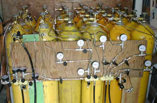
Overview of the fill-station. A few more HC-4500 bottles have
joined since this picture was taken |
 |
The four rows on the right are the 4 air banks. The HC-4500
bottles are on the far right row. Note the line above the bottles in
the very back connecting the first three air banks - this is the check-valved
line that enables cascaded bank-filling from the compressor. The 4500
PSI bank is isolated from the others and filled through the air manifold
only. Also notice on the left-most air bank (front three bottles) that
I ran out of NPT female tees and resorted to using tube tees instead. |
 |
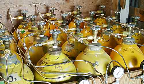
These left-most two rows comprise all the non-air storage bottles.
The front-most four bottles comprise a 4-bottle oxygen cascade. Behind
them, are the trimix and nitrox storage bottles. The two bottles at
the far back make up the 2-bottle helium cascade. |
 |
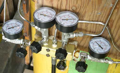
This is the oxygen manifold. Each gauge/valve runs to a separate
cylinder |
 |
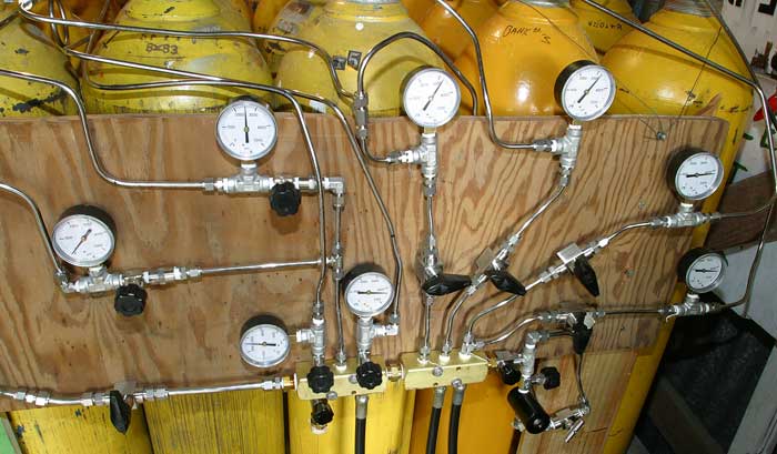
This is the air & mix manifold. The right-half manifold combines lines from 4
air banks, all controlled by ball valves. The left-half of the manifold
ties in all the nitrox/trimix/helium cylinders. Since the mixed gases are
generally used for remixing, these lines are controlled by needle valves for
precision flow control. If needed, the ball valve at the lower left allows
oxygen in from the oxygen manifold for partial-pressure nitrox mixing without
having to switch hoses.
|
GO TO PAGE:
1 - Introduction
2 - Bank Bottles
3 - Fittings 4
- Tubing 5 - Valves
6 - Manifolds, whips, gauges,O2-cleaning
A handful of good supply sources


